
Marine Navigation Services: Safe Waterways
Differential Global Positioning System (DGPS) in Canada
On December 15th, 2022, the Canadian Coast Guard has permanently discontinue the provision of its DGPS service across Canada.
Discontinuing this service aligns with Coast Guard’s efforts to modernize marine navigation services and find alternatives to aging DGPS infrastructures.
(A users guide to the design, maintenance and safe use of waterways)
Part 1(a)
Guidelines for the Safe Design of Commercial Shipping Channels
Published by the Waterways Development Division,
Canadian Coast Guard
On this page
- Introduction
- 1.0 Input Parameters - Waterway Dimensions
- 2.0 Width
- 3.0 Depth
- 4.0 Side Slope
- 5.0 Bends
- 6.0 Bridge Clearance
- 7.0 Economic Optimum Design
- Bibliography
Introduction
In navigable waterways where the vessel traffic is expected to make use of the full water depth and width, it is necessary to ensure that a careful balance is achieved between the need to accommodate the user (thus maximising economic benefits to the industry) and the paramount need to maintain adequate safety allowances. This involves analyses and full account of the interrelations between the parameters of the vessels, the waterway and weather factors. In addition, other factors, such as frequency of siltation, maintenance requirements, availability of navigational aid, pilotage, dredgate disposal options (if dredging is considered), as well as economic and environmental impacts, all need to be considered.
This document provides planners with a set of procedures to be used when determining waterway parameters required to provide efficient manoeuvrability with no less than minimum safety margins and allowances. Procedures are set forth for the determination of channel width, depth, side slope and curvature, as well as the alignment of channels.
The guidelines have been developed for waterways utilized primarily by large traffic, such as tankers, general cargo and bulk carriers, and are not meant to replace more extensive analyses for the final channel design. As with the application of any guidelines, good judgement, experience and common sense will be required in their application.
The methods are based upon the operational requirements for ships, and the aim is to provide the conceptual requirements for safe and efficient navigation. The design procedure for each element of waterway geometry is provided in order to enable the planner to optimize the design.
For the purposes of this document, the expressions "waterway" and "channel" have the same meaning.
1.0 Input Parameters - Waterway Dimensions
The input variables required, as a minimum, to determine the minimum waterway dimensions required for safe navigation are as follows:
1.1 Vessel
The critical component in the design of the waterway is the selection of the "target" vessel . In evaluating the waterway manoeuvring parameters, the target vessel is normally the largest vessel that the waterway is expected to accommodate safely and efficiently. The parameters required for the target vessel are:
- length (L);
- beam (B);
- maximum draught (d);
- speed (vs);
- manoeuvrability - a qualitative determination of the vessel's manoeuvrability in comparison with other vessels; and
- traffic density - the level of traffic frequenting the waterway.
1.2 Waterway
The waterway parameters, or waterway characteristics, are determined from field programs or existing information. They are as follows:
- bottom material characteristics;
- depth;
- current velocity and direction;
- wind velocity and direction;
- wave height; and
- navigation aid/pilot service.
1.3 Baseline Study Data
Input data is captured from baseline studies that are undertaken involving an analysis and evaluation of the following:
Target vessel and other deep-draught vessels using the waterway:
- dimensions (length, beam, draught);
- manoeuvrability and speed;
- number and frequency of use; and
- type of cargo handled.
Other traffic using the waterway:
- types of smaller vessels and congestion; and
- cross traffic.
Weather:
- wind (velocity, direction and duration);
- waves (heights, period, direction and duration);
- visibility (rain, smog, fog and snow, including duration and frequency of impairment);
- ice (frequency, duration and thickness); and
- abnormal water levels (high or low).
Characteristics of a waterway:
- currents, tidal and/or river (velocity, direction, and duration);
- sediment sizes and area distribution, movement, and serious scour and shoal areas;
- type of bed and bank (soft or hard);
- alignment and configuration;
- freshwater inflow;
- tides;
- salinity;
- dredged material disposal areas;
- temperature;
- water quality;
- biological population (type, density, distribution and migration);
- obstructions (such as sunken vessels and abandoned structures);
- existing bridge and powerline crossings (location, type and clearances);
- waterway constrictions; and
- submerged cables and pipelines.
The input parameters are used to develop the requirements and design considerations for channel width and depth, as demonstrated in the flow chart shown in Figure 1. Figure 2 and Figure 3 provide more detail on the width and depth parameters.
1.4 Water Level
The depth of the waterway should be adequate to accommodate the deepest-draught vessel expected to use the waterway. However, this is not the case 100 percent of the time; it may be possible to schedule passage of the deepest-draught vessel during high water levels (i.e., high tide). Selection of the design draught should be based on an economic analysis of the cost of vessel delays, operation and light loading compared with construction and maintenance cost. Footnote 1.
Relevant Parameters
- Width
- Manoeuvring Lane
- Vessel Clearance
- Bank Suction
- Wind Effect
- Current Effect
- Channel with Bends
- Navigational Aids / Pilot
- Depth
- Draught
- Trim
- Squat
- Exposure Allowance
- Fresh Water Adjustment
- Manoeuvrability Allowance
- Overdepth Allowance
- Depth Transition
- Tidal Allowance
Width Parameters
- Manoeuvring Lane
- Vessel type and size controllability
- Vessel Clearance
- Vessel size
- Operational experience
- Bank Suction
- Ration of channel width / vessel beam
- Ration of channel depth / vessel draught
- Wind Effect
- Vessel size, loaded or in ballast
- Wind direction, wind speed / vessel speed
- Vessel draught / channel depth
- Current Effect
- Vessel size, loaded or in ballast
- Current direction, current speed / vessel speed
- Channel with Bends
- Vessel size, speed, turning angle, controllability
- Radius of curvature, sight distance
- Curve transition and curve alignments
- Navigational Aids / Pilot
Depth Parameters
- Draught
- Vessel static draught
- Trim
- Vessel length
- Squat
- Vessel speed, draught
- Channel depth, block coefficient
- Exposure allowance
- Vessel size, traffic density, local wave climate
- Fresh water adjustment
- Water salinity and vessel size
- Manoeuvrability allowance
- Channel bottom, operational character
- Vessel Speed, ocontrollability
- Overdepth allowance
- Nature of channel bottom
- Dredging tolerance and siltation
- Depth transition
- Sudden changes in channel depth
- Tidal allowance
- Reference datum
- Highest and lowest level tidal window
2.0 Width
This section describes the procedure for determining the channel width required in straight sections. The calculation for the channel bends is provided in Section 5.
The basis for the variables included in the equations is the waterway target vessel. The total channel width refers to the horizontal distance measured from the toe-to-toe side slopes at the design depth. Total width is expressed as:
Total Width = Design Width + Allowances
Design Width refers to the summation of width requirements for:
- ship manoeuvring;
- hydrodynamic interactions between meeting and passing vessels in two-way traffic;
- counteracting crosswinds and cross current;
- counteracting bank suction; and
- navigational aids (including pilots).
Allowances refer to additional width increases to compensate for bank slumping and erosion, sediment transport and deposition, as well as the type of bank material. (See Figure 4) Footnote 1
2.1 Manoeuvring Lane
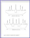
Figure 4
The manoeuvring lane is the width required to allow for the oscillating track produced by the combination of sway and yaw of the vessel. The oscillation is partly due to forces acting on a moving ship, such as directional instability and response to rudder action, and the human response to course deviations.
Manoeuvring lane widths should be calculated for the largest of the most frequently expected vessel type, and the resulting largest lane should be adopted as the required manoeuvring lane width. In some cases, depending on the traffic structure, the channel width may accommodate two-way traffic for a certain range of vessel sizes and one way traffic for a larger range of traffic.
Frequency of channel use by vessel classes can be used to determine the probability of the width that would be required. This can also be optimised through operation of the vessel traffic services and traffic scheduling.
In the design of the manoeuvrability lane, an assessment has to be made of the target vessel manoeuvring characteristics. Table 1 shows the assumptions used to arrive at an assessment of the vessel's manoeuvrability and the resulting lane requirements. Depending on the type of target vessel, a “manoeuvrability coefficient” is multiplied by the target vessel's beam (B) to determine the manoeuvring lane width.
Manoeuvrability Coefficients for Various Vessel Types Footnote 2
- Naval fighting vessels, Victory class freighters
- Manoeuvrability: Excellent
- Manoeuvrability Coefficient: 1.3
- Manoeuvring Lane Width: 1.3 B
- Tankers, new ore ships, Liberty class freighters
- Manoeuvrability: Good
- Manoeuvrability Coefficient: 1.5
- Manoeuvring Lane Width: 1.5 B
- Old ore ships, damaged vessels
- Manoeuvrability: Poor
- Manoeuvrability Coefficient: 1.8
- Manoeuvring Lane Width: 1.8 B
Where B = "target" vessel beam Footnote 1, Footnote 5, Footnote 8, Footnote 9, Footnote 12, Footnote 13
Note:
For the majority of the preliminary designs for which this guideline is intended, the vessel can be assumed to have "Good" manoeuvrability.
2.2 Hydrodynamic Interaction Lane (Ship Clearance)
As two vessels pass, there are strong interaction forces between them, giving rise to path deviations and heading changes. Even though the interaction forces are quite large, the magnitudes of the path deviations and heading changes during the actual passing of the vessels are small. The real danger lies after the vessels have passed when the dynamic disturbances imparted to the vessels during passing can combine with bank effects and lead to oscillating diverging motions if not properly controlled.
The minimum hydrodynamic interaction width desired is 30 metres (100 feet). The recommended approach is:
Vessel Clearance = 1 B, if B > 30 m
or
Vessel Clearance = 30 m, if B < 30 m Footnote 1, Footnote 5, Footnote 7, Footnote 9, Footnote 12
Encounter traffic density should also be considered in two-way traffic channels. Additional width is required for channels with heavy traffic density. The requirements for traffic density are shown below in Table 2.
| Traffic Density | Width Requirement |
|---|---|
| Light (0 - 1.0 vessel/hour) | 0.0 B |
| Moderate ( 1.0 - 3.0 vessel/hour ) | 0.2 B |
| Heavy ( > 3.0 vessel /hour) | 0.4 B |
Note:
The vessels considered exclude small craft such as pleasure and fishing vessels. The values per hour are not necessarily daily means; peak periods should be considered when analysing traffic patterns.
2.3 Wind and Current Effects
Wind forces on a vessel produce two effects: a sideways drift and a turning moment. The former is overcome by steering a course to counteract it, and the latter is overcome by applying a certain amount of helm. Counteracting the drift will induce vessel yaw; this requires a widening of the channel.
The degree to which wind affects a vessel depends on the relative direction of the wind, the ratio of wind speed to vessel speed, the depth to draught ratio and whether the vessel is loaded or in ballast.
Winds from the bow are generally not a concern for wind speeds less than 10 times the vessel speed. However, winds become a greater concern as the wind shifts abeam. The maximum effect occurs perpendicular to the ship's beam.
The yaw angle caused by wind is most severe for a vessel in ballast. Therefore, it is the ballast condition that is used to determine the additional channel width required for wind effects. The width requirement for wind effects is shown in Table 3 below.
| Wind Severity | Width Requirement for vessel Manoeuvrability | ||
|---|---|---|---|
| Excellent | Good | Poor | |
| Low (< 15 knots) | 0.0 B | 0.0 B | 0.0 B |
| Moderate (15 - 33 knots) | 0.3 B | 0.4 B | 0.5 B |
| Severe (> 33 knots) | 0.6 B | 0.8 B | 1.0 B |
| Where B = "target" vessel beam Footnote 5, Footnote 8, Footnote 13 | |||
The influence of cross current on a vessel principally follows similar requirements as those for crosswinds, as shown in Table 4 below.
| Current Severity | Width Requirement for vessel Manoeuvrability | ||
|---|---|---|---|
| Excellent | Good | Poor | |
| Negligible ( < 0.2 knots ) | 0.0 B | 0.0 B | 0.0 B |
| Low ( 0.2 - 0.5 knots ) | 0.1 B | 0.2 B | 0.3 B |
| Moderate ( 0.5 - 1.5 knots ) | 0.5 B | 0.7 B | 1.0 B |
| Severe ( > 1.5 knots ) | 0.7 B | 1.0 B | 1.3 B |
| Where B = "target" vessel beam Footnote 5, Footnote 8, Footnote 13 | |||
2.4 Bank Suction Requirement (Bank Clearance)
When a ship moves through water, the water is displaced at the bow and transported back around the hull to fill the void behind the stern. Flow produced lateral pressures are balanced when the ship is proceeding in an open channel or on the centre line of a symmetrical channel. However, when the ship is moving parallel to, but off the channel centre-line, the forces are asymmetrical resulting in a yawing moment. The yawing moment is produced by the building of a wave system between the bow and the near channel bank. Behind this bow wave, the elevation of the water between the vessel and the near bank is less than between the vessel and the centre line of the channel with a force being produced tending to move the stern toward the near bank. This effect is called bank suction and increases directly with the distance the sailing line is from the centre line of the channel.
The magnitude of the bank suction effect is influenced by a number of factors:
- The distance of the vessel from the bank-theory and tests indicate that the magnitude of the lateral force varies approximately as a function of the cube of the distance.
- The magnitude of the forces increases with decreasing depth/draught ratios and increasing speed.
- Studies also indicate that the ratio of bank height/channel depth has considerable impact on bank effects. Bank suction forces reduce rapidly as the ratio decreases. Shallower bank slopes also help to reduce bank effects.
As for the assessment of the manoeuvring lane width, the determination of the bank suction requirement is a function of the vessel manoeuvrability, speed, wind and current. It is also a function of the bank material. Table 5 is a guide for the determination of the bank suction requirements.
| Vessel ManoeuvrabilityFootnote 3 | Width Requirement - Severity | ||
|---|---|---|---|
| Low | Medium | High> | |
| Excellent | 0.5 B | 0.75 B | 1.0 B |
| Good | 0.75 B | 1.0 B | 1.25 B |
| Poor | 1.0 B | 1.25 B | 1.5 B |
| Where B = "target" vessel beam Footnote 1, Footnote 9, Footnote 12 | |||
2.5 Navigational Aids Requirement/Pilots Service
The determination of the navigational aids requirements is a function of the complexity of the channel and the navigational aids provided along its length. If, for example, the navigational aids are spaced such that the ship's Captain/Pilot can visually ascertain the channel dimensions through the use of ranges and buoys, then no additional width is required. Therefore, the development of the channel dimensions and the placements of aids should be undertaken concurrently. Table shows the additional width requirements according to the status of navigational aids. This table also includes the availability of pilots which will have a definite influence on the additional width requirement.
| Navigational Aids | Width Requirement |
|---|---|
| Excellent | 0.0 B |
| Good | 0.1 B |
| Moderate with infrequent poor visibility | 0.2 B |
| Moderate with frequent poor visibility | 0.5 B |
2.6 Other Allowances
The previous topics cover the major concerns with the design of the channel width. There are, however, additional items that should be considered in the assessment of the required width of the channel.
Vessel Cargo
In this day of environmental consciousness, the designer should consider the vessel cargo as part of the evaluation of waterway safety and the associated risks. For instance, if the majority of the traffic is crude versus bulk grain, the designer should provide a channel width that makes the chance of grounding or interaction a rare event with an annual probability of occurrence of 1 x 10 5. The present approach is to address this issue through the use of navigational aids. Table 7 shows the requirement for type of cargo for a one-lane channel.
| Cargo hazard level | Width Requirement |
|---|---|
| Low | 0.0 B |
| Medium | 0.5 B |
| High | 1.0 B |
Depth of the Waterway
Sufficient channel depth is required to maintain vessel manoeuvrability. A simple way to account for this is to set a minimum value for water depth/draught ratio. In many parts of the world, a value of 1.10 has become acceptable, although a value of 1.15 is also often used. The closer the ratio is to unity, the more directionally stable (i.e., difficult to alter course) is the ship and, consequently, the more sluggish its response. It is usual practice to allow for this by increasing channel width. The width requirement for the depth/draught ratio is shown in Table 8.
| Depth / Draught Ratio (D/d) | Width Requirement |
|---|---|
| D/d > 1.50 | 0.0 B |
| 1.15 ≤ D/d≤ 1.50 | 0.2 B |
| D/d <1.15 | 0.4 B |
Channel Bottom Surface
The effect of bottom surface is important only in shallow waterways. If the depth is more than 1.5 times the draught of the design ship, no additional width is needed. A guide for the bottom surface requirements is shown in Table 9.
| Bottom Surface | Width Requirement | |
|---|---|---|
| D/d > 1.5 | D/d < 1.5 | |
| Smooth and soft | 0.0 B | 0.0 B |
| Smooth or sloping and hard | 0.1 B | 0.2 B |
| Smooth or sloping and hard | 0.5 B | 0.7 B |
Night Time Transit and Fog Effect
The effect of vessel visibility in the channel is another parameter that needs to be qualitatively evaluated by the designer. The designer should take into consideration the number of fog free days when considering channel width requirements. With the development of global positioning systems and differential global positioning systems to enhance the reliance of vessel navigation, this parameter may be of lesser importance.
Vessel Speed
The vessel speed is another parameter to be considered in the width design. However, this parameter is of minor importance since the suggested additional width is 0.1 B for speeds higher than 12 knots. For that reason, it was not included in the width calculation software. This does not mean, however, that it should be systematically ignored; specific site conditions may suggest otherwise.
3.0 Depth
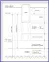
Figure 5
Minimum Waterway Depth for safe navigation is calculated from the sum of the draught of the design vessel as well as a number of allowances and requirements as seen in the following formula:
Actual Waterway DepthFootnote 4 = Target Vessel Static Draught + Trim + Squat + Exposure Allowance + Fresh Water Adjustment + Bottom Material Allowance + Overdepth Allowance + Depth Transition - Tidal Allowance, (see Figure 5: Components of Waterway Depth)
Project (Advertised) Waterway Depth = Waterway Depth - Overdepth Allowance
In addition to the factors affecting Waterway Depth included in this section, others that should also be taken into account include:
- the effect of currents in the waterway;
- the effect of water levels in the waterway and adjoining water bodies, by such changes as river flow and wind set up;
- environmental effects; and
- limiting depths elsewhere in the waterway.
In the determination of the design draught, it should be realised that the depth does not necessarily have to be available 100 percent of the time. This may require the deepest-draught vessel to schedule passage during high water levels. Selection of the design depth should be based on an economic analysis of the cost of vessel delays, operation and light load, compared with construction and maintenance costs.
3.1 Target Vessel Static Draught
The draught of the target vessel that will be using the waterway is based on the anticipated ship traffic for the proposed waterway. These dimensions are selected by an economic evaluation of the ship traffic for the waterway.
3.2 Trim
Trim is generally defined as the longitudinal inclination of a ship, or the difference in draught from the bow to the stern. It is controlled by loading. In general, at low speed, a ship underway will squat by the bow. The practice is to counteract this squat by trimming the ship by the stern when loading. The rule of thumb is to provide an allowance of 0.31 m to account for trim in waterway design Footnote 5, Footnote 9.
The normal approach for a vessel is to assume a trim rate of 3"/100 ft of length or 0.25 m/100 m Footnote 3, Footnote 5, Footnote 9.
3.3 Tidal Allowance
The selection of an allowance for tidal effect should be derived from examination of a statistically significant sample of tidal records during the navigation season to determine to what extent tidal height above the chart datum should be included as part of the normally available water depth. The allowance selected should give the required level of waterway availability based on tidal scheduling determined through optimization analysis.
3.4 Squat
Squat refers to the increase of a ship's draught as a result of its motion through water. It is a hydraulic phenomenon whereby the water displaced creates an increase in current velocity past the moving hull causing a reduction in pressure resulting in a localised reduction of the water level and, consequently, in a settling of the vessel deeper in the water. For various reasons-having to do with hull design, trim and other physical and operational factors-squat may be different at the fore and aft.
Recently, a new equation was developed on the basis of extensive research by Waterways Development to specifically target commercial waterways with vessel traffic and conditions representative of most major Canadian waterways. This equation takes into account the vessel beam in relation to the channel width, contrary to earlier equations that supposed infinite width. This new parameter is of importance since most Canadian waterways have limited width. The equation, known as Eryuzlu Equation # 3, is therefore recommended as the one providing the most reliable results in waterways of limited dimensions. The equation is written as follows:
![Calculation: Z(d/D^2)= a[Vs/(gd)^½]^b [D/d]^C (Fw)](/publications/waterways-voies-navigables/images/eq1.jpg)
where:
Z = squat;
d = vessel draught;
D = channel depth;
Vs = vessel speed;
g = gravity acceleration;
W = channel width;
B = vessel beam; and
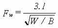
Fw = channel width factor.
With Fw = 1, where W > 9.61 B;
a, b, c are common coefficients:
a = 0.298, b = 2.289, c = -2.972
where W < 9.61 B; and
The equation is non-dimensional and therefore, can be used universally with any system of measurement units.
Applications
The formula applies for:
- vessels ranging from 19,000 DWT to 227,000 DWT, representing general cargo or crude carriers (block coefficient over 0.80);
- a channel that is shallow and relatively straight;
- the channel width may range from unrestricted to four times the vessel beam;
- speeds ranging from about 2 knots to about 14 knots;
- maximum trim of about 10 % of draft;
- the predominant squat is fore squat; and
- vessel loaded draft equal to or greater than 80% of the registered draft.
Formulae, by definition, tend to generalize the real situation. Therefore, good judgement, experience and common sense are required in the use of this and any formula.
3.5 Depth Allowance for Exposure
The selection of the exposure allowance should take into account the movements of heaving, pitching and rolling caused by local conditions, and should be based on available information on the local wave climate and vessel traffic considerations.
The allowance should be selected so as to minimize arrival and departure delays accounting for economic considerations. If a substantial allowance is required for a minimal reduction in delays or the delay problems are minimal with low traffic, the allowance can be omitted. However, for other cases, the supplementary depth can be based on the information provided in Table 10. (Larger values may be required in waterways on the East and West Coasts).
| Exposure | Depth Allowance |
|---|---|
| Unexposed | 0 m |
| Medium Exposure | 0.15 m |
| Fully Exposed | 0.30 m |
3.6 Fresh Water Adjustment
Salinity increases the density of water, in turn reducing the draught of the vessel in the waterway. Design of the waterway depth should account for fluctuations in the salinity that may occur in an estuary exposed to tidal influences and river discharges. An adjustment for fresh water should account for the decreased buoyancy of the vessel.
A rule of thumb to determine the additional loading allowance for vessels in fresh water is to set it at 2-3% of the salt water draught Footnote 1, Footnote 5,Footnote 9.
3.7 Bottom Material Allowance
This allowance, also known as the Net Underkeel Clearance, is by definition the minimum safety margin between the keel of the vessel and the project (advertised) waterway depth. This allowance is provided in addition to the allowances for squat, trim, freshwater and the influence of the design wind and wave conditions in order to ensure a safety margin against striking the bottom. The value is a function of the nature of the bottom, the handling characteristics of the vessel and the operational character of the waterway. Table 11 summarises the values that may be used as a function of the Bottom Material.
| Bottom Material | Depth Allowance |
|---|---|
| Soft | 0.25 m |
| Medium (Sand) | 0.60 m |
| Hard Bottom (Rock) | 0.90 m |
3.8 Manoeuvrability Margin
The Manoeuvrability Margin is made up of the allowance for bottom material (or the Net Underkeel Clearance) and the exposure allowance. This margin is a measure of the minimum required to allow the vessel to manoeuvre adequately in the waterway. A minimum margin of 1.0 m is generally used for the operation of large vessels. Therefore, the sum of the Bottom Material Allowance and Exposure Allowance should be at least 1.0 m to accommodate the Manoeuvrability Margin for vessels of 250,000 DWT and greater Footnote 10.
3.9 Overdepth Allowance
Overdepth Allowance refers to an allowance to account for waterway siltation between dredging and tolerance of sounding and dredging.
The dredging tolerance varies with the type of dredging plant employed and the bottom conditions. The average acceptable tolerance is 0.3 m. If the bottom material is soft and can be displaced by a ship, no tolerance allowance is necessary Footnote 1.
An allowance for siltation is usually based on the anticipated accumulation patterns of the silt. The allowance is designed to accommodate the siltation between dredging operations.
3.10 Depth Transition
All reaches of the waterway must be examined and depths set according to the varying conditions encountered. This, and the natural bathymetry of the waterway, will lead to the provision of different depths in adjacent sections of the waterway.
If the transition between adjacent reaches is large, the sudden change in Underkeel Clearance will have an effect on the current velocities and hydrostatic pressure on the hull. The result will be a change in the ship's performance, manoeuvrability and draught.
Vessel squat in a transition area is presently being evaluated by Waterways Development. The preliminary analysis shows that the squat would increase by 15% to 20% when the transition is from deep water to shallow water.
4.0 Side Slope
The selection of a suitable side slope is necessary to reduce waterway maintenance and for protection of vessels. In order to minimize hull damage, a maximum side slope of 1:1 is recommended to allow some movement of the vessel up the bank in the event of a collision. Table 12 provides a guide to the maximum slopes for stability. Slope stability analyses should be undertaken to ensure the factor of safety of the slope is greater than 1.25.
| Soil Material | Side Slope H:V |
|---|---|
| All Materials, minimum required side slopes | 1:1 |
| Firm Rock | 1:1 |
| Fissured rock, more or less disintegrated rock, tough hardpan | 1:1 |
| Cemented gravel, stiff clay soils, ordinary hardpan | 1:1 |
| Firm, gravely, clay soil | 1:1 |
| Average loam, gravely loam | 3:2 |
| Firm clay | 3:2 |
| Loose sandy loam | 2:1 |
| Very sandy soil | 3:1 |
| Sand and gravel, without or with little fines | 3:1 - 4:1 |
| Sand and gravel with fines | 4:1 - 5:1 |
| Muck and peat soil | 4:1 |
| Mud and soft silt | 6:1 - 8:1 |
5.0 Bends
Bends in channels should only be employed where absolutely necessary because of the difficult navigation conditions that result from the imbalance in flow and velocity with changes in the channel direction. This, in turn, creates moment and hydrodynamic forces that increase steering difficulty of the vessel transiting the bend.
Design of the channel bend should account for: a radius of curvature that reflects the vessel's turning ability; an increase in width to accommodate the manoeuvring difficulties encountered; transition zones from the straight channel section to the widened bend; and proper alignment.
5.1 Radius of Curvature
The radius of curvature for the channel bend must be designed for the poorest turning vessel that is likely to use the channel. The main factors affecting a vessel's turning ability are Underkeel Clearance, block coefficient, rudder area ratio and trim.
Where bends are necessary in a channel, Table 13 provides the minimum requirements that should be applied for ships to proceed without tug assistance at a speed of 10 kts or to avoid widening approach to bend.
| Angle of Turn | Radius of Curvature |
|---|---|
| Less than 25º | 3 L |
| 25º - 35º | 5 L |
| 35º - 55º | 8 L |
| Greater than 55º | 10 L |
| Where L = target vessel length (Ref: 5, 7, 8, 11) | |
However, for radius values below the figures in Table 13 and requiring more than 20% of rudder, tug assistance should be considered.
Bends with radii of 10 L or more are considered minor (i.e., navigationally, they are considered straight channels requiring no widening through the bend) Footnote 11.
5.2 Width
In the cases when the radius of curvature is not minor, a supplementary width has to be added to the ship lane width of the straight channel to account for manoeuvring difficulties, as well as incertitude with respect to the vessel's path while transiting the bend. There is a sideslip that occurs which depends mainly on the depth/draught ratio (D/d). This slip causes the vessel to sweep out a path wider than its beam; this excess varies from approx. 0.3B at D/d= 1.1 to 1.6B in deep water . The magnitude of the width increase is also a function of the vessel turning angle, radius of curvature, sight distance, environmental conditions, as well as the length, beam, speed and manoeuvrability of the vessel. The following equation for determining the increase in channel width in bends was developed from the Dave Taylor Model Basin studies:
![Calculation: ?W= [ (0.9144 F ) (Vs)^2 L^2 F ] / [ Rt Cc S ]](/publications/waterways-voies-navigables/images/eq3.jpg)
Where:
W = increase in the ship lane width, (m);
Φ = angle of turn, degrees;
Vs = speed of ship in channel relative to the bottom, (kts);
L = ship length, (m);
Rt = turning radius, (m);
Cc = coefficient of vessel manoeuvrability (turning ability) (poor = 1; good = 2; very good = 3);
S = unobstructed sight distance from the bridge of the ship, (metres); and
F = 1.0 for one way traffic; 2.0 for two way traffic.
The minimum required sight distance, S, was determined by navigators during the Panama Canal studies to be 2446 m (1.52 statute miles) Footnote 5, Footnote 9.
Due to the difficulty in predicting the hydrodynamic forces as a vessel transits a gradually widening bend-especially when currents are flowing-it is recommended that the width of the channel should remain constant throughout the bend.
The increased channel width in a bend may be undertaken by one of three methods: (a) the cut-off method; (b) the parallel banks' method; and (c) the non-parallel banks' method Footnote 5. The cut-off method has been used for the St. Lawrence Seaway and has the advantage of requiring less dredging than the other methods. The Panama Canal studies, however, found that for certain applications the cut-off method produced undesirable current patterns Footnote 9.
In those areas where the minimum requirements for radius cannot be met and the channel cannot be widened, tug assistance shall be required.
5.3 Transitions
A transition zone from the straight section of the channel to the increased width of the bend is required to provide for the increasing asymmetric forces exerted on the ship as it enters the turn. The ends of zones having different widths should be joined by straight lines of length at least equal to the reach of the target vessel Footnote 11, but not less than a length/additional width ratio of 10:1 to provide a smoother change from the straight section to the widened cross section of the bend. The widening of the channel should occur on the straight portions of the channel and not on the bend itself. Figure provides an explanation of the vessel reach calculations.
Figure summarises the criteria for dimensioning a parallel widened channel bend.
Transitions - Design Example
Find the transition length for a channel bend widened to an additional 20 m when,
Vessel speed, vs = 4.12 m/s (8 kts)
Turning lag, T = 30 seconds
Reach = T x vs = 30 x 4.12 = 123.5 m
Compare to the ratio of transition length/additional width (Lt/Wa)
123.5/20 = 6:1 < 10:1
Reach = 20 x 10
= 200 m
Therefore, the length of the transition is 200 m, since the recommended minimum ratio is 10:1. Table 14 provides some recommended transition ratios for vessels based on their manoeuvrability.
| Vessel Manoeuvrability | Transition Ratio |
|---|---|
| Excellent | 10:1 |
| Good | 10:1 |
| Poor | 15:1 |
5.4 Distance between curves
A straight section should be available between the end of one curve and the start of another curve equal to at least five times the target vessel's length. Further, reverse curves should be avoided. Footnote 1

Figure 6
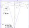
Figure 7
6.0 Bridge Clearance
6.1 General
Bridge clearance should be sufficient to permit safe transit of the maximum-size vessel expected to use the waterway.
6.2 Horizontal Clearance
The horizontal bridge clearance selected should consider the following:
- traffic density and whether one-way or two-way traffic and/or overtaking will be permitted;
- alignment and velocity of the current;
- risk of collisions;
- consequences of collision because of hazardous cargo, damage to bridge and vessel and interruption of waterway and bridge traffic; and
- cost of bridge pier protection against ramming (in recent years, computer modelling has been used to determine horizontal clearances based on probabilistic methods for measuring deviation from the ships' intended paths) Footnote 1.
6.3 Vertical Clearance
The vertical clearance is the distance from the water surface to the lowest member of the bridge structure. A water level that is exceeded only two percent or less of the time during the life of the project is a reasonable design criteria for determining the near maximum surface for a heavily used channel. The distance between the top of the vessel and the lowest member of the bridge is dependent upon the vessel's motion characteristics and should be at least 3 m.
7.0 Economic Optimum Design
For larger traffic in limited-depth waterways, reconciliation between safety and efficiency becomes a complex challenge, both to the regulatory and operational agencies. For the regulatory agencies, it is extremely important to ensure that safety is not compromised for the sake of efficiency. For the operational agencies, it is equally important that efficiency is not compromised in order to optimize safety.
The optimum design of a waterway requires studies of the estimated costs and benefits of various plans and alternatives considering safety, efficiency and environmental impact. These studies are used to determine the most economical and functional channel alignment and design considering initial dredging, maintenance and replacement costs for different design levels Footnote 1.
The economic optimization of a waterway requires study of several alignments and channel dimensions (width and depth) that are acceptable for safe and efficient navigation. Costs are developed for the alignment and dimension for each alternative. Benefits are determined by transportation savings with consideration of vessel trip time and tonnage, delays for tides, weather conditions and the effects of reduced depths in waterways that have rapid shoaling tendencies.
Bibliography
- Date modified: